Warning
This is an unpolished draft of the second edition of this ebook. If you find any error or have suggestions to improve the text, please create an issue via https://github.com/obonaventure/cnp3/issues?milestone=9
The IPv6 subnet
Until now, we have focussed our discussion on the utilisation of IPv6 on point-to-point links. Although there are point-to-point links in the Internet, mainly between routers and sometimes for endhosts, most of the endhosts are attached to datalink layer networks such as Ethernet LANs or WiFi networks. These datalink layer networks play an important role in today’s Internet and have heavily influenced the design of the operation of IPv6. To understand IPv6 and ICMPv6 completely, we first need to correctly understand the key principles behind these datalink layer technologies.
As explained earlier, devices attached to a Local Area Network can directly exchange frames among themselves. For this, each datalink layer interface on a device (endhost, router, ...) attached to such a network is identified by a MAC address. Each datalink layer interface includes a unique hardwired MAC address. MAC addresses are allocated to manufacturers in blocks and interface is numbered with a unique address. Thanks to the global unicity of the MAC addresses, the datalink layer service can assume that two hosts attached to a LAN have different addresses. Most LANs provide an unreliable connectionless service and a datalink layer frame has a header containing :
- the source MAC address
- the destination MAC address
- some multiplexing information to indicate the network layer protocol that is responsible for the payload of the frame
LANs also provide a broadcast and a multicast service. The broadcast service enables a device to send a single frame to all the devices attached to the same LAN. This is done by reserving a special broadcast MAC address (typically all bits of the address are set to one). To broadcast a frame, a device simply needs to send a frame whose destination is the broadcast address. All devices attached to the datalink network will receive the frame.
The broadcast service allows to easily reach all devices attached to a datalink layer network. It has been widely used to support IP version 4. A drawback of using the broadcast service to support a network layer protocol is that a broadcast frame that contains a network layer packet is always delivered to all devices attached to the datalink network, even if some of these devices do not support the network layer protocol. The multicast service is a useful alternative to the broadcast service. To understand its operation, it is important to understand how a datalink layer interface operates. In shared media LANs, all devices are attached to the same physical medium and all frames are delivered to all devices. When such a frame is received by a datalink layer interface, it compares the destination address with the MAC address of the device. If the two addresses match, or the destination address is the broadcast address, the frame is destined to the device and its payload is delivered to the network layer protocol. The multicast service exploits this principle. A multicast address is a logical address. To receive frames destined to a multicast address in a shared media LAN, a device captures all frames having this multicast address as their destination. All IPv6 nodes are capable of capturing datalink layer frames destined to different multicast addresses.
Interactions between IPv6 and the datalink layer
IPv6 hosts and routers frequently interact with the datalink layer service. To understand the main interactions, it is useful to analyze all the packets that are exchanged when a simple network containing a few hosts and routers is built. Let us first start with a LAN containing two hosts [1].
![graph foo {
randkir=LR;
lan;
A [color=white, shape=box label=<<TABLE border="0" cellborder="0">
<TR><TD width="45" height="60" fixedsize="true"><IMG SRC="icons/host.png" scale="true"/></TD></TR><TR><td>A<br/>MAC : 0023:4567:89ab</td></TR>
</TABLE>>];
B [color=white, shape=box label=<<TABLE border="0" cellborder="0">
<TR><TD width="45" height="60" fixedsize="true"><IMG SRC="icons/host.png" scale="true"/></TD></TR><TR><td>B<br/>MAC : 0034:5678:9abc</td></TR>
</TABLE>>];
A--lan;
B--lan;
}](../_images/graphviz-5e9efd2590bb6b06972edae5d92e1cb211238a8c.png)
Hosts A and B are attached to the same datalink layer network. They can thus exchange frames by using the MAC addresses shown in the figure above. To be able to use IPv6 to exchange packets, they need to have an IPv6 address. One possibility would be to manually configure an IPv6 address on each host. However, IPv6 provides a better solution thanks to the link-local IPv6 addresses. A link-local IPv6 address is an address that is composed by concatenating the fe80:://64 prefix with the MAC address of the device. In the example above, host A would use IPv6 link-local address fe80::0223:45FF:FE67:89ab and host B fe80::0234:5678:9aFF:FEbc:dede. With these two IPv6 addresses, the hosts can exchange IPv6 packets.
Note
Converting MAC addresses in host identifiers
Appendix A of RFC 4291 provides the algorithm used to convert a 48 bits MAC address into a 64 bits host identifier. This algorithm builds upon the structure of the MAC addresses. A MAC address is represented as shown in the figure below.
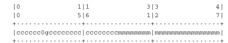
A MAC address
MAC addresses are allocated in blocks of  . When a company registers for a block of MAC addresses, it receives an identifier. company identifier is then used to populated the c bits of the MAC addresses. The company can allocate all addresses in starting with this prefix and mangages the m bits as it wishes.

A MAC address converted into a 64 bits host identifier
Inside a MAC address, the two bits indicated as 0 and g in the figure above play a special role. The first bit indicates whether the address is universal or local. The g bit indicates whether this is a multicast address or a unicast address. The MAC address can be converted into a 64 bits host identifier by flipping the value of the 0 bit and inserting FFFE, i.e. 1111111111111110 in binary, in the middle of the address as shown in the figure below. The c, m and g bits of the MAC address are not modified.
The next step is to connect the LAN to the Internet. For this, a router is attached to the LAN.
![graph foo {
randkir=LR;
lan;
A [color=white, shape=box label=<<TABLE border="0" cellborder="0">
<TR><TD width="45" height="60" fixedsize="true"><IMG SRC="icons/host.png" scale="true"/></TD></TR><TR><td>A<br/>MAC : 0023:4567:89ab</td></TR>
</TABLE>>];
B [color=white, shape=box label=<<TABLE border="0" cellborder="0">
<TR><TD width="45" height="60" fixedsize="true"><IMG SRC="icons/host.png" scale="true"/></TD></TR><TR><td>B<br/>MAC : 0034:5678:9abc</td></TR>
</TABLE>>];
router[color=white, label=<<TABLE border="0" cellborder="0">
<TR><TD width="75" height="30" fixedsize="true"><IMG SRC="icons/router.png" scale="true"/></TD></TR><TR><td>router<br/>0045:6789:abcd</td></TR>
</TABLE>>];
A--lan;
B--lan;
router--lan;
}](../_images/graphviz-16a58626169694ad9319c9781e9993da5485dbab.png)
Assume that the LAN containing the two hosts and the router is assigned prefix 2001:db8:1234:5678/64. A first solution to configure the IPv6 addresses in this network is to assign them manually. A possible assignment is :
- 2001:db8:1234:5678::1 is assigned to router
- 2001:db8:1234:5678::AA is assigned to hostA
- 2001:db8:1234:5678::BB is assigned to hostB
To be able to exchange IPv6 packets with hostB, hostA needs to know the MAC address of the interface of hostB on the LAN. This is the address resolution problem. In IPv6, this problem is solved by using the Neighbor Discovery Protocol (NDP). NDP is specified in RFC 4861. This protocol is part of ICMPv6 and uses the multicast datalink layer service.
NDP allows a host to discover the MAC address used by any other host attached to the same LAN. NDP operates in two steps. First, the querier sends a multicast ICMPv6 Neighbor Solicitation message that contains as parameter the queried IPv6 address. This multicast ICMPv6 NS is placed inside a multicast frame [2]. The queried node receives the frame, parses it and replies with a unicast ICMPv6 Neighbor Advertisement that provides its own IPv6 and MAC addresses. Upon reception of the Neighbor Advertisement message, the querier stores the mapping between the IPv6 and the MAC address inside its NDP table. This table is a data structure that maintains a cache of the recently received Neighbor Advertisement. Thanks to this cache, a host only needs to send a Neighbor Sollicitation message for the first packet that it sends to a given host. After this initial packet, the NDP table can provide the mapping between the destination IPv6 address and the corresponding MAC address.
![msc {
router [label="router", linecolour=black],
hostA [label="hostA", linecolour=black],
hostB [label="hostB", linecolour=black];
hostA->* [ label = "NS : Who has 2001:db8:1234:5678::BB" ];
hostB->hostA [ label = "NA : 1234:5678:9abc:dede"];
|||;
}](../_images/mscgen-1845ec349cfa29dc011f7d56f6b4db6dc2157e84.png)
The NS message can also be used to verify the reachability of a host in the local subnet. For this usage, NS messages can be sent in unicast since other nodes on the subnet do not need to process the message.
When an entry in the NDP table times out on a host, it may either be deleted or the host may try to revalidate it by sending the NS message again.
This is not the only usage of the Neighbor Solicitation and Neighbor Advertisement messages. They are also used to detect the utilization of duplicate addresses. In the network above, consider what happens when a new host is connected to the LAN. If this host is configured by mistake with the same address as hostA (i.e. 2001:db8:1234:5678::AA), problems could occur. Indeed, if two hosts have the same IPv6 address on the LAN, but different MAC addresses, it will be difficult to correctly reach them. IPv6 anticipated this problem and includes a Duplicate Address Detection Algorithm (DAD). When an IPv6 address [3] is configured on a host, by any means, the host must verify the uniqueness of this address on the LAN. For this, it multicasts an ICMPv6 Neighbor Solicitation that queries the network for its newly configured address. The IPv6 source address of this NS is set to :: (i.e. the reserved unassigned address) if the host does not already have an IPv6 address on this subnet). If the NS does not receive any answer, the new address is considered to be unique and can safely be used. Otherwise, the new address is refused and an error message should be returned to the system administrator or a new IPv6 address should be generated. The Duplicate Address Detection Algorithm can prevent various operational problems that are often difficult to debug.
Few users manually configure the IPv6 addresses on their hosts. They prefer to rely on protocols that can automatically configure their IPv6 addresses. IPv6 supports two such protocols : DHCPv6 and the Stateless Address Autoconfiguration (SLAAC).
The Stateless Address Autoconfiguration (SLAAC) mechanism defined in RFC 4862 enables hosts to automatically configure their addresses without maintaining any state. When a host boots, it derives its identifier from its datalink layer address [4] as explained earlier and concatenates this 64 bits identifier to the FE80::/64 prefix to obtain its link-local IPv6 address. It then multicasts a Neighbour Solicitation with its link-local address as a target to verify whether another host is using the same link-local address on this subnet. If it receives a Neighbour Advertisement indicating that the link-local address is used by another host, it generates another 64 bits identifier and sends again a Neighbour Solicitation. If there is no answer, the host considers its link-local address to be valid. This address will be used as the source address for all NDP messages sent on the subnet.
To automatically configure its global IPv6 address, the host must know the globally routable IPv6 prefix that is used on the local subnet. IPv6 routers regularly multicast ICMPv6 Router Advertisement messages that indicate the IPv6 prefix assigned to the subnet. The Router Advertisement message contains several interesting fields.

Format of the ICMPv6 Router Advertisement message
This message is sent from the link-local address of the router on the subnet. Its destination is the IPv6 multicast address that targets all IPv6 enabled hosts (i.e. ff02::1). The Cur Hop Limit field, if different from zero, allows to specify the default Hop Limit that hosts should use when sending IPv6 from this subnet. 64 is a frequently used value. The M and O bits are used to indicate that some information can be obtained from DHCPv6. The Router Lifetime parameter provides the expected lifetime (in seconds) of the sending router acting as a default router. This lifetime allows to plan the replacement of a router by another one in the same subnet. The Reachable Time and the Retrans Timer parameter are used to configure the utilisation of the NDP protocol on the hosts attached to the subnet.
Several options can be included in the Router Advertisement message. The simplest one is the MTU option that indicates the MTU to be used within the subnet. Thanks to this option, it is possible to ensure that all devices attached to the same subnet use the same MTU. Otherwise, operational problems could occur. The Prefix option is more important. It provides information about the prefix(es) that is (are) advertised by the router on the subnet.

The Prefix information option
The key information placed in this option are the prefix and its length. This allows the hosts attached to the subnet to automatically configure their own IPv6 address. The Valid and Preferred Lifetimes provide information about the expected lifetime of the prefixes. Associating some time validity to prefixes is a good practice from an operational viewpoint. There are some situations where the prefix assigned to a subnet needs to change without impacting the hosts attached to the subnet. This is often called the IPv6 renumbering problem in the literature RFC 7010. A very simple scenario is the following. An SME subscribes to one ISP. Its router is attached to another router of this ISP and advertises a prefix assigned by the ISP. The SME is composed of a single subnet and all its hosts rely on stateless address configuration. After a few years, the SME decides to change of network provider. It connects its router to the second ISP and receives a different prefix from this ISP. At this point, two prefixes are advertised on the SME’s subnet. The old prefix can be advertised with a short lifetime to ensure that hosts will stop using it while the new one is advertised with a longer lifetime. After sometime, the router stops advertising the old prefix and the hosts stop using it. The old prefix can now be returned back to the first ISP. In larger networks, renumbering an IPv6 remains a difficult operational problem [LeB2009].
Upon reception of this message, the host can derive its global IPv6 address by concatenating its 64 bits identifier with the received prefix. It concludes the SLAAC by sending a Neighbour Solicitation message targeted at its global IPv6 address to ensure that no other host is not using the same IPv6 address.
Note
Router Advertisements and Hop Limits
ICMPv6 Router Advertisements messages are regularly sent by routers. They are destined to all devices attached to the local subnet and no router should ever forward them to another subnet. Still, these messages are sent inside IPv6 packets whose Hop Limit is always set to 255. Given that the packet should not the forwarded outside of the local subnet, the reader could expect instead a Hop Limit set to 1. Using a Hop Limit set to 255 provides one important benefit from a security viewpoint and this hack has been adapted in several Internet protocols. When a host receives a Router Advertisement message, it expects that this message has been generated by a router attached to the same subnet. Using a Hop Limit of 255 provides a simple check for this. If the message was generated by an attacker outside the subnet, it would reach the subnet with a decremented Hop Limit. Checking that the Hop Limit is set to 255 is a simple [5] verification that the packet was generated on this particular subnet. RFC 5082 provides other examples of protocols that use this hack and discuss its limitations.
Routers regularly send Router Advertisement messages. These messages are triggered by a timer that is often set at approximately 30 seconds. Usually, hosts wait for the arrival of a Router Advertisement message to configure their address. This implies that hosts could sometimes need to wait 30 seconds before being able to configure their address. If this delay is too long, a host can also send a Router Solicitation message. This message is sent towards the multicast address that corresponds to all IPv6 routers (i.e. FF01::2) and the default router will reply.
The last point that needs to be explained about ICMPv6 is the Redirect message. This message is used when there is more than one router on a subnet as shown in the figure below.
![graph foo {
randkir=LR;
lan;
A [color=white, shape=box label=<<TABLE border="0" cellborder="0">
<TR><TD width="45" height="60" fixedsize="true"><IMG SRC="icons/host.png" scale="true"/></TD></TR><TR><td>A<br/>MAC : 0023:4567:89ab</td></TR>
</TABLE>>];
B [color=white, shape=box label=<<TABLE border="0" cellborder="0">
<TR><TD width="45" height="60" fixedsize="true"><IMG SRC="icons/host.png" scale="true"/></TD></TR><TR><td>B<br/>MAC : 0034:5678:9abc</td></TR>
</TABLE>>];
router1[color=white, label=<<TABLE border="0" cellborder="0">
<TR><TD width="75" height="30" fixedsize="true"><IMG SRC="icons/router.png" scale="true"/></TD></TR><TR><td>router1<br/>0045:6789:abcd</td></TR>
</TABLE>>];
router2[color=white, label=<<TABLE border="0" cellborder="0">
<TR><TD width="75" height="30" fixedsize="true"><IMG SRC="icons/router.png" scale="true"/></TD></TR><TR><td>router2<br/>0012:3456:7878</td></TR>
</TABLE>>];
A--lan;
B--lan;
router1--lan;
router2--lan;
}](../_images/graphviz-90a23c06439b1877c8417b9af4fb1c090d89419f.png)
In this network, router1 is the default router for all hosts. The second router, router2 provides connectivity to a specific IPv6 subnet, e.g. 2001:db8:abcd::/48. These two routers attached to the same subnet can be used in different ways. First, it is possible to manually configure the routing tables on all hosts to add a route towards 2001:db8:abcd::/48 via router2. Unfortunately, forcing such manual configuration boils down all the benefits of using address auto-configuration in IPv6. The second approach is to automatically configure a default route via router1 on all hosts. With such route, when a host needs to send a packet to any address within 2001:db8:abcd::/48, it will send it to router1. router1 would consult its routing table and find that the packet needs to be sent again on the subnet to reach router2. This is a waste of time. A better approach would be to enable the hosts to automatically learn the new route. This is possible thanks to the ICMPv6 Redirect message. When router1 receives a packet that needs to be forwarded back on the same interface, it replies with a Redirect message that indicates that the packet should have been sent via router2. Upon reception of a Redirect message, the host updates it forwarding table to include a new transient entry for the destination reported in the message. A timeout is usually associated with this transient entry to automatically delete it after some time.
An alternative is the Dynamic Host Configuration Protocol (DHCP) defined in RFC 2131 and RFC 3315. DHCP allows a host to automatically retrieve its assigned IPv6 address, but relies on server. A DHCP server is associated to each subnet [6]. Each DHCP server manages a pool of IPv6 addresses assigned to the subnet. When a host is first attached to the subnet, it sends a DHCP request message in a UDP segment (the DHCP server listens on port 67). As the host knows neither its IPv6 address nor the IPv6 address of the DHCP server, this UDP segment is sent inside a multicast packet target at the DHCP servers. The DHCP request may contain various options such as the name of the host, its datalink layer address, etc. The server captures the DHCP request and selects an unassigned address in its address pool. It then sends the assigned IPv6 address in a DHCP reply message which contains the datalink layer address of the host and additional information such as the subnet mask, the address of the default router or the address of the DNS resolver. The DHCP reply also specifies the lifetime of the address allocation. This forces the host to renew its address allocation once it expires. Thanks to the limited lease time, IP addresses are automatically returned to the pool of addresses when hosts are powered off.
Both SLAAC and DHCPv6 can be extended to provide additional information beyond the IPv6 prefix/address. For example, RFC 6106 defines options for the ICMPv6 ND message that can carry the IPv6 address of the recursive DNS resolver and a list of default domain search suffixes. It is also possible to combine SLAAC with DHCPv6. RFC 3736 defines a stateless variant of DHCPv6 that can be used to distribute DNS information while SLAAC is used to distribute the prefixes.
Footnotes
| [1] | For simplicity, you assume that each datalink layer interface is assigned a 64 bits MAC address. As we will see later, today’s datalink layer technologies mainly use 48 bits MAC addresses, but the smaller addresses can easily be converted into 64 bits addresses. |
| [2] | RFC 4291 and RFC 4861 explain in more details how the IPv6 multicast address is determined from the target IPv6 unicast address. These details are outside the scope of this book, but may matter if you try to understand a packet trace. |
| [3] | The DAD algorithm is also used with link-local addresses. |
| [4] | Using a datalink layer address to derive a 64 bits identifier for each host raises privacy concerns as the host will always use the same identifier. Attackers could use this to track hosts on the Internet. An extension to the Stateless Address Configuration mechanism that does not raise privacy concerns is defined in RFC 4941. These privacy extensions allow a host to generate its 64 bits identifier randomly every time it attaches to a subnet. It then becomes impossible for an attacker to use the 64-bits identifier to track a host. |
| [5] | Using a Hop Limit of 255 prevents one family of attacks against ICMPv6, but other attacks still remain possible. A detailed discussion of the security issues with IPv6 is outside the scope of this book. It is possible to secure NDP by using the Cryptographically Generated IPv6 Addresses (CGA) defined in RFC 3972. The Secure Neighbour Discovery Protocol is defined in RFC 3971. A detailed discussion of the security of IPv6 may be found in [HV2008]. |
| [6] | In practice, there is usually one DHCP server per group of subnets and the routers capture on each subnet the DHCP messages and forward them to the DHCP server. |