Warning
This is an unpolished draft of the second edition of this ebook. If you find any error or have suggestions to improve the text, please create an issue via https://github.com/obonaventure/cnp3/issues?milestone=2
Network : Open questions
In your daily life, you also use hierarchical and flat address spaces. Can you provide examples of these two types of addresses and discuss the benefits of using a hierarchical or flat addressing space in this particular context ?
The network below uses port forwarding with flat addresses. The network boots and all hosts start one after the other. Explain at each step how the packets are forwarded and how the port forwarding tables of the network nodes are modified. Host C sends a packet to host B. Some time later, host A sends a packet to host C. Finally, host B sends a packet to host A.
![\tikzstyle{arrow} = [thick,->,>=stealth]
\tikzset{router/.style = {rectangle, draw, text centered, minimum height=2em}, }
\tikzset{host/.style = {circle, draw, text centered, minimum height=2em}, }
\tikzset{ftable/.style={rectangle, dashed, draw} }
\node[host] (A) {A};
\node[router, right=of A] (R1) { R1 };
\node[router,right=of R1] (R2) {R2};
\node[router,below=of R1] (R3) {R3};
\node[host, right=of R3] (B) {B};
\node[host, below=of B] (C) {C};
\path[draw,thick]
(A) edge (R1)
(R1) edge (R2)
(R2) edge (R3)
(R3) edge (C)
(R3) edge (B);](_images/tikz-5999954acae9845e1806f90e9287dcf864d2ce65.png)
Same question as above, but the network is modified as shown in the figure below.
![\tikzstyle{arrow} = [thick,->,>=stealth]
\tikzset{router/.style = {rectangle, draw, text centered, minimum height=2em}, }
\tikzset{host/.style = {circle, draw, text centered, minimum height=2em}, }
\tikzset{ftable/.style={rectangle, dashed, draw} }
\node[host] (A) {A};
\node[router, right=of A] (R1) { R1 };
\node[router,right=of R1] (R2) {R2};
\node[router,below=of R1] (R3) {R3};
\node[host, right=of R3] (B) {B};
\node[host, below=of B] (C) {C};
\path[draw,thick]
(A) edge (R1)
(R1) edge (R2)
(R2) edge (R3)
(R3) edge (R1)
(R3) edge (C)
(R3) edge (B);](_images/tikz-d5e80ee59a768c856ca9bfd67f00c5f75d705d83.png)
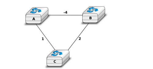
Routing protocols used in data networks only use positive link weights. What would happen with a distance vector routing protocol in the network below that contains a negative link weight ?
A simple network
- When a network specialist designs a network, one of the problems that he needs to solve is to set the metrics the links in his network. In the USA, the Abilene network interconnects most of the research labs and universities. The figure below shows the topology of this network in 2009.
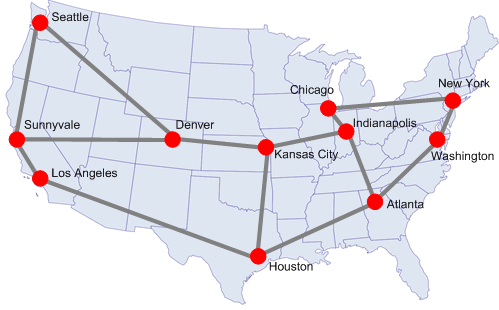
The Abilene network
In this network, assume that all the link weights are set to 1. What is the paths followed by a packet sent by the router located in Los Angeles to reach :
- the router located in New York
- the router located in Washington ?
Is it possible to configure the link metrics so that the packets sent by the router located in Los Angeles to the routers located in respectively New York and Washington do not follow the same path ?
Is it possible to configure the link weights so that the packets sent by the router located in Los Angeles to router located in New York follow one path while the packets sent by the router located in New York to the router located in Los Angeles follow a completely different path ?
Assume that the routers located in Denver and Kansas City need to exchange lots of packets. Can you configure the link metrics such that the link between these two routers does not carry any packet sent by another router in the network ?
- In the five nodes network shown below, can you configure the link metrics so that the packets sent by router E to router A use link B->A while the packets sent by router B use links B->D and D->A?

Simple five nodes network
- In the five nodes network shown above, can you configure the link weights so that the packets sent by router E (resp. F) follow the E->B->A path (resp. F->D->B->A) ?
- Consider the network shown in the figure below.
Assuming that the network uses source routing, what are the possible paths from R1 to R4 ?
![\tikzset{router/.style = {rectangle, draw, text centered, minimum height=2em}, }
\tikzset{host/.style = {circle, draw, text centered, minimum height=2em}, }
\node[router] (R2) {R2};
\node[router, below left=of R2] (R1) {R1};
\node[router, below right=of R2] (R3) {R3};
\node[router, below right=of R1] (R4) {R4};
\path[draw,thick]
(R1) edge (R2)
(R2) edge (R3)
(R3) edge (R1)
(R1) edge (R4)
(R4) edge (R3);](_images/tikz-2c49658bb6f201a1278e9c66a5273c1f9396461f.png)
- Consider the network shown in the figure below.
The network operator uses would like to have the following paths in this network :
- R3->R2->R4->R5 and R1->R2->R5
Is it possible to achieve these paths and if so what are the required forwarding tables ?
Same question with virtual circuits.
![\tikzset{router/.style = {rectangle, draw, text centered, minimum height=2em}, }
\tikzset{host/.style = {circle, draw, text centered, minimum height=2em}, }
\node[router] (R3) {R3};
\node[router, below left=of R3] (R1) {R1};
\node[router, below right=of R3] (R2) {R2};
\node[router, above right=of R2] (R4) {R4};
\node[router, below right=of R4] (R5) {R5};
\path[draw,thick]
(R1) edge (R2)
(R2) edge (R3)
(R3) edge (R1)
(R2) edge (R4)
(R4) edge (R5)
(R2) edge (R5);](_images/tikz-fcc960ea2aea74463169d275f2f35d36f9f48350.png)
- Consider the network shown in the figure below.
The network operator would like to use the following paths :
- R1->R2->R4 and R3->R2->R5->R4
Are these paths possible with link-state or distance vector routing ? If yes, how do configure the link weights. If no, explain your answer.
Same question with virtual circuits.
![\tikzset{router/.style = {rectangle, draw, text centered, minimum height=2em}, }
\tikzset{host/.style = {circle, draw, text centered, minimum height=2em}, }
\node[router] (R3) {R3};
\node[router, below left=of R3] (R1) {R1};
\node[router, below right=of R3] (R2) {R2};
\node[router, above right=of R2] (R4) {R4};
\node[router, below right=of R4] (R5) {R5};
\path[draw,thick]
(R1) edge (R2)
(R2) edge (R3)
(R3) edge (R1)
(R2) edge (R4)
(R4) edge (R5)
(R2) edge (R5)
(R3) edge (R4);](_images/tikz-f171b6207e8a7ac0ebf294afb42d71676c2f9771.png)
- Consider the network shown in the figure below.
The network operator would like to use the following paths :
- R1->R5->R4 and R3->R2->R4
Are these paths possible with link-state or distance vector routing ? If yes, how do configure the link weights. If no, explain your answer.
![\tikzset{router/.style = {rectangle, draw, text centered, minimum height=2em}, }
\tikzset{host/.style = {circle, draw, text centered, minimum height=2em}, }
\node[router] (R3) {R3};
\node[router, below left=of R3] (R1) {R1};
\node[router, below right=of R3] (R2) {R2};
\node[router, above right=of R2] (R4) {R4};
\node[router, below right=of R4] (R5) {R5};
\path[draw,thick]
(R1) edge (R2)
(R2) edge (R3)
(R3) edge (R1)
(R2) edge (R4)
(R4) edge (R5)
(R2) edge (R5)
(R1) edge [bend right] (R5);](_images/tikz-5d470a4774ac50306738a58f08699c7bbf255bcb.png)
Network: Discussion questions
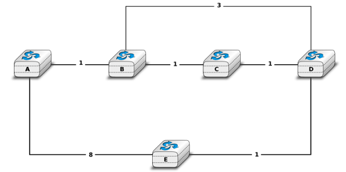
The network below uses port forwarding tables. It has been running for several hours and all hosts have exchanged packets. What is the content of the port forwarding tables ?
![\tikzstyle{arrow} = [thick,->,>=stealth]
\tikzset{router/.style = {rectangle, draw, text centered, minimum height=2em}, }
\tikzset{host/.style = {circle, draw, text centered, minimum height=2em}, }
\tikzset{ftable/.style={rectangle, dashed, draw} }
\node[host] (A) {A};
\node[router, right=of A] (R1) {R1};
\node[router,right=of R1] (R2) {R2};
\node[router,below=of R1] (R3) {R3};
\node[host, right=of R3] (B) {B};
\node[host, below=of B] (C) {C};
\path[draw,thick]
(A) edge (R1)
(R1) edge (R2)
(R2) edge (R3)
(R3) edge (C)
(R3) edge (B);](_images/tikz-8cc783874e7a4d73b2cb3cb6688654850284cd0b.png)
At this point, a new link is added between R1 and R3. What happens for the forwarding of packets ?
The network below uses port forwarding tables. What happens if host A moves by removing its link with R1 and replacing it with a link with R3? How should networks using port forwarding deal with such mobile hosts ?
Some hosts need to be multihomed, i.e. attached to two different network nodes as shown in the figure below.
Would this network work correctly with port-forwarding tables if :
- Host A uses the same flat address for both links.
- Host A uses a different flat address on each of its links
![\tikzstyle{arrow} = [thick,->,>=stealth]
\tikzset{router/.style = {rectangle, draw, text centered, minimum height=2em}, }
\tikzset{host/.style = {circle, draw, text centered, minimum height=2em}, }
\tikzset{ftable/.style={rectangle, dashed, draw} }
\node[host] (A) {A};
\node[router, right=of A] (R1) {R1};
\node[router,right=of R1] (R2) {R2};
\node[router,below=of R1] (R3) {R3};
\node[host, right=of R3] (B) {B};
\node[host, below=of B] (C) {C};
\path[draw,thick]
(A) edge (R1)
(A) edge (R3)
(R1) edge (R2)
(R2) edge (R3)
(R3) edge (C)
(R3) edge (B);](_images/tikz-441a335b22e2161b5398b134c99dc90da12f9a40.png)
- What are the advantages and drawbacks of flat addresses versus hierarchical addresses ?
- Let us now consider the transient problems that mainly happen when the network topology changes. For this, consider the network topology shown in the figure below and assume that all routers use a distance vector protocol that uses split horizon.
Simple network with redundant links
If you compute the routing tables of all routers in this network, you would obtain a table such as the table below :
Destination Routes on A Routes on B Routes on C Routes on D Routes on E A 0 1 via A 2 via B 3 via C 4 via D B 1 via B 0 1 via B 2 via C 3 via D C 2 via B 1 via C 0 1 via C 2 via D D 3 via B 2 via C 1 via D 0 1 via D E 4 via B 3 via C 2 via D 1 via E 0 Distance vector protocols can operate in two different modes : periodic updates and triggered updates. Periodic updates is the default mode for a distance vector protocol. For example, each router could advertise its distance vector every thirty seconds. With the triggered updates a router sends its distance vector when its routing table changes (and periodically when there are no changes).
- Consider a distance vector protocol using split horizon and periodic updates. Assume that the link B-C fails. B and C update their local routing table but they will only advertise it at the end of their period. Select one ordering for the periodic updates and every time a router sends its distance vector, indicate the vector sent to each neighbor and update the table above. How many periods are required to allow the network to converge to a stable state ?
- Consider the same distance vector protocol, but now with triggered updates. When link B-C fails, assume that B updates its routing table immediately and sends its distance vector to A and D. Assume that both A and D process the received distance vector and that A sends its own distance vector, ... Indicate all the distance vectors that are exchanged and update the table above each time a distance vector is sent by a router (and received by other routers) until all routers have learned a new route to each destination. How many distance vector messages must be exchanged until the network converges to a stable state ?
- Consider again the network shown above. After some time, link state routing converges and all routers compute the same routing tables as above.
An important difference between OSPF and RIP is that OSPF routers flood link state packets that allow the other routers to recompute their own routing tables while RIP routers exchange distance vectors. Consider that link B-C fails and that router B is the first to detect the failure. At this point, B cannot reach anymore C, D and E. C cannot reach B and A anymore.
Router B will flood its updated link state packet through the entire network and all routers will recompute their forwarding table. Upon reception of a link state packet, routers usually first flood the received link-state packet and then recompute their forwarding table. Assume that B is the first to recompute its forwarding table, followed by D, A, C and finally E.
- After each update of a forwarding table, verify which pairs of routers are able to exchange packets. Provide your answer using a table similar to the one shown above.